Exhaust flames coming out of a 2013 Honda Shadow Phantom with Vance & Hines Shortshots.
Exhaust flames coming out of a 2013 Honda Shadow Phantom with Vance & Hines Shortshots.
2013 Honda Shadow Phantom (VT750C2B)
Baffles removed and straight pipe welded in place of the baffles to tune the hollow sound out of the pipe.
THIS WAS JUST AWESOME, that's all I gotta say. I had a lot of fun and met my heroes like J Scott Campbell, Frank Capullo, and Frank Cho and have gotten their autographs. We met Stan Lee for just a brief second but was still enough to give us a nerdgasm. He commented on our costumes and said they were pretty awesome. By the way we've never made any costumes before so we decided to try something new.


The chair is finally finished. I still haven't gotten the professional pictures back from the photographer but when I do I will post them up


Ok so my chair for the WilsonArt Lamination contest is actually almost done but I forgot to take pictures of it completely laminated. These are the updates though of the lamination in progress. Each of the triangle braces weren't the same (because of my inability to make multiples of triangle braces perfectly) so I marked each one on the chair and chiseled it away with a hammer I machined from scratch and my trusty CRKT M-21 Knife. That's right I chiseled it with my knife and they turned pretty good. The lamination is difficult because of the weird angles I had to custom cut each piece exactly instead of having the laminate overlap and cutting it off with a router.


Heres some of the highlights from my shitty jam session with my buddy Paul Sadauskas (Real badass drummer). Bear with the recordings they were done with my iPhone and theres only two of us playing (Guitar and drums) so the music will sound like it's missing something but here it is, hope you like it. Keep in mind that this is just a spontaneous jam so everything is just on the fly.
My chair is coming along. I have the arms and seat together now and have been trying out the fit. As I was testing the fit and comfort, I came up with a better solution to my design. I know it's not good to change up right in the middle of the build but I have this new design all ready to go. Instead of making the chair use the same principle as the Z-Chair. I wanted to make the chair rock back and forth on a pivot. It's easier to look at the pictures then to write a whole book on here explaining how it works.


My entry for the WilsonArt Contest is currently in the works. I couldn't afford the metal so I had to change up the design and material choices. My chair is now being created out of wood and because of the angles, I had to add braces onto each angle. This is the progress so far on the chair, I'll keep posting as the chair progresses.


This is a model of a thumbdrive I designed in Solidworks rendered in Hypershot.


This is a model of an organic chair in Solidworks rendered in Hypershot. I was learning and experimenting with drawing organic shapes in solidworks which if you know solidworks is no easy task.


These are the pictures of everyone's mockups for the WilsonArt Competition.
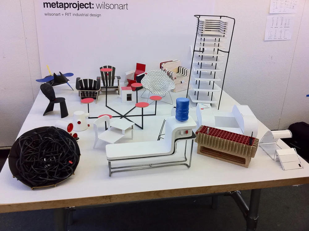


This is the final mockup I made for my WilsonArt Chair Entry for the Thought Incubation chair and RIT's Metaproject.


These are engine stands that I have designed and built for multiple UAV engine's for Eastcor Engineering (http://www.eastcoreng.com/). The stands have no metal in them for testing purposes and had to be strong enough to run the engines with the propellers on them at full speed. I used the these stands to test and check for any kind of underlying RF signature that the engines would give off. The idea was that each engine, even of the same model would give off a unique harmonic frequency much like an aircraft carrier or destroyer naval ship. We found that engines all gave off what seemed a unique signature but overall was a fail. The signal wasn't strong enough to be captured over longer distances (flight distance).
These are the original 30 concept paintings for my chair entry (The Reverie) for the WilsonArt Chair competition.
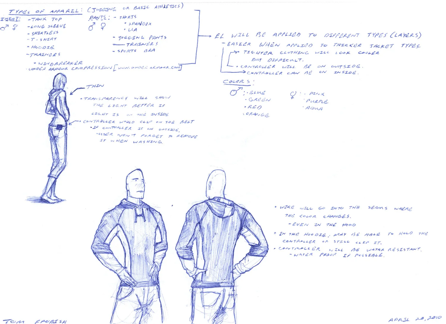
This is the new research that I've done and brought my idea back up. I stated back near ground one again and was taking in what you saying on our previous conversation. The images have descriptions attached to them explaining each page. The only ones with out a description is the photos I took the mini models.
Ok, so I'm making this alarm for my physical computing class that basically wakes you up by turning on a high powered light that would rotate over your wall or your body to create a false sunset for those of you who wake up to light.
Basically what I've been working on was taking an alarm clock, my trusty arduino, a wireless wall switch and relay, a 4' 2000 lumen led flourescent replacement bulb, some servos, and some pvc tubing. In a very fast summary, my friend Jason and I wired them together and pressed a couple of keys in the keyboard to tell the light to turn on and swivel when the arduino recieves signal the alarm going off.
So far, I have not finished the project because for some reason, I have been very retarded and couldn't find the right signal off of the alarm clock board that triggered the speaker to go off. I kept thinking I can use the buzzer lines themselves but was very confused when I found that they had a constant 3.2 volts running through the line when the buzzer wasn't going off and when the buzzer did go off, the voltage dropped down to 2 volts which baffled me for a very long time. Then when I called my dad to see if he knew what might be happening, he said to try checking it on AC current and I was like...uh ok, when I did skeptically, I the voltage jumped up to 1 volt AC when the buzzer went off, which means it really wasn't a buzzer, but an actual speaker (which runs off of AC current, not DC) which would explain why it wasn't making any noise when it had 3.2 volts running through it.
After a lot of searching for the trigger signal coming out of the little microprocessor, I couldn't actually find a line that jumped up to a high when the alarm went off. Every line that had voltage change went from a constant high and dropped down to a low. So I decided instead of trying to find a high to signal the arduino, I would just tell it to send out a low signal to to wireless transmitter when receiving a high and send out a high when it received a low from the alarm clock.
Then after being braindead and having a cheapass soldering iron, I went on to surface mount a lead off of one of the resistors (normally this would be peace of cake if I had the right tools and was in the right mind) but I had a cheap soldering iron with a blunt pencil tip and because of it's low heat, I had to hold it onto the board for an extended amount of time (don't worry, I used flux) and it heated the other resistors around it and caused a few to pop. Then Murphy's law kicked in hardcore because after that happened, I managed to get them soldered back on. After that, the wire I leaded off of the other resistor (was an 18awg wire solid core, that's all I had at the time) broke off and took half of the resistor with it. After just staring at what just happened for a few minutes, I figured "Well shit, maybe if I just solder the two halves together, maybe the board won't know." and I think between that and popping some of the other resistors and heating the other components up I figured and broke something or shorted something else because when I go to check the clock, now it's got a power drain somewhere because the line that was supposed to be outputting 3.2 volts was putting out 2.6 volts and didn't drop when the buzzer went off which was totally awesome!
Anyways, I summarize the rest of the project, when the alarm clock went off, it would tell the arduino it was beeping, then the arduino would switch a transitor on the wireless switch which would flip the latching relay hooked into the wall to turn on and turn the light on. When that would happen, the arduino would then tell the servos to run their script (which was slowly rotate the bulb of the bed and blind the sleeping person awake.


Alright, so I've been designing this new idea for awhile and that was to create some kind of safety clothing that would be both stylish and very visible at night or in heavy fog or anything that the user would want to be seen in. I recently come across Electroluminescent Wire (EL Wire) which produces and constant and seamless light along a wire. It comes in many sizes and is pretty cheap.
Anyways after much searching, I started going through many different concepts and ideas of how I'm going to stylize the clothing. I've seen a lot of clothing for halloween costumes that light up but they all look very cheesy. Running around like Tron may look cool in the movie but in real life...yeah.
I've been focusing on the simplicity that Under Armor has for their clothing and decided to make the lights follow a two tone pattern the runs along the body. I've posted different concepts and some of the thinking pages (if you actually want to spend the time to read those too :P)
I've also posted at diary of this project on youtube so that I can link it over to this blog:
http://www.youtube.com/watch?v=Ki9AUvcoTTw
The clothing and final design basically came out to be a simple two tone running jacket that runs along the arms in a spiral pattern and around the shoulders. When the light is off, noone would be able to tell the jacket has been modified, but when it turns on, it really draws a lot of attention. Another thing I really liked about the wire was the fact that it was very bright at night but when you entered a lighted area, it was like it wasn't even on.
Also the other reason for the blue color was in bioluminesence, blue actually travels the farthest of all of the colors with the least amount of energy. Also the light blue color stands out the most to peripheral vision.


Alrighty, so I'm finally posting the code I made for the light sensor circuit. If you can read C++ then the schematic is basically posted in the code. Essentially, the code just reads the resistance from the photo resistor and depending on the range, it'll light up the corresponding light. To help with a smoother transistion between the reads, I also told the arduino to smooth the data meaning it'll take the average of every 10 samples.
I will make this is the summer and link the vid on here from youtube since I can't post videos on this blog.
If you want to make a light sensor, here's the code to do it (All you'd need to do is change the "if" "else" values to calibrate the sensor):
const int numReadings = 10;
const int ledPin = 13;
const int ledBlue = 5;
const int ledYellow = 4;
const int ledGreen = 3;
const int ledOrange = 2;
const int ledRed = 8;
int readings[numReadings];
int index = 0;
int total = 0;
int average = 0;
int inputPin = 0;
void setup()
{ Serial.begin(9600);
for (int thisReading = 0; thisReading
readings[thisReading] = 0;
pinMode(ledPin, OUTPUT);
pinMode(ledBlue, OUTPUT);
pinMode(ledYellow, OUTPUT);
pinMode(ledGreen, OUTPUT);
pinMode(ledOrange, OUTPUT);
pinMode(ledRed, OUTPUT);
pinMode(inputPin, INPUT);
}
void loop() {
total= total - readings[index];
readings[index] = analogRead(inputPin);
total= total + readings[index];
index = index +1;
if (index >= numReadings)
index = 0;
average = total / numReadings;
Serial.println(average, DEC);
if (average < 506)
{digitalWrite(ledRed, LOW);}
else {digitalWrite(ledRed, HIGH);}
if (average < 489 || average >= 506)
{digitalWrite(ledOrange, LOW);}
else {digitalWrite(ledOrange, HIGH);}
if (average < 472 || average >= 489)
{digitalWrite(ledYellow, LOW);}
else {digitalWrite(ledYellow, HIGH);}
if (average < 455 || average >= 472)
{digitalWrite(ledGreen, LOW);}
else {digitalWrite(ledGreen, HIGH);}
if (average < 438 || average >= 455)
{digitalWrite(ledBlue, LOW);}
else {digitalWrite(ledBlue, HIGH);}
if (average < 421 || average >= 438)
{digitalWrite(ledPin, LOW);}
else {digitalWrite(ledPin, HIGH);}
}
The first thing for Physical computing we had to do was create some kind of circuit, so I decided to kind of go a little farther. I created a night light circuit that has problems :P Basically the circuit is supposed to turn on automatically in the dark and turn off in the daytime but can be turned on by pressing the button. I'm not actually sure what's going on at the moment. The LED never fully turns off and it and only gets brighter when you press the switch. I don't know if this is a characteristic of the 74ls00 (Quad NAND Gate)chip or not but when I check it it's putting out a constant 1.4-1.6 volts and when I press the switch it puts out 3v (I have a little 3v coin battery on it) I'm pretty sure the chip is supposed to send out zero voltage when putting out a Low Signal.
Since the 74ls00 chip can only supply like 24mv it's not strong enough to supply the LED to the brightness and it could hurt the chip so I put on a transistor to basically create a gate that activates when the chip sends it a High signal and routes power directly from the battery instead of through the chip.
So attached are the different revisions of the schematic and some poor quality photos of the breadboard. I'll update with a cleaner setup, I have to put the circuit back together.


